Step-By-Step Guide to Testing Cable Continuity With a Multimeter for Longevity
You’ll want a digital multimeter like those from Fluke or AstroAI-they beep instantly when continuity’s present, making tests fast and reliable. Set it to continuity mode (diode symbol with sound waves), touch probe tips to exposed wire ends, and check for a beep or near-zero ohms. No beep? Look for breaks or corrosion. Wiggle the cable to catch intermittent faults. Even with solid continuity, signal issues can persist due to poor shielding-keep that in mind as you explore further.
Notable Insights
- Power off all connected devices to ensure safety and prevent damage during continuity testing.
- Set the multimeter to continuity mode, indicated by the diode-and-sound symbol, for audible feedback.
- Test each conductor individually by touching probe tips firmly to metal contacts at both cable ends.
- Listen for a beep or check for near-zero resistance, confirming unbroken electrical pathways.
- Wiggle the cable during testing to reveal intermittent faults that compromise long-term reliability.
What Is Cable Continuity and Why It Matters
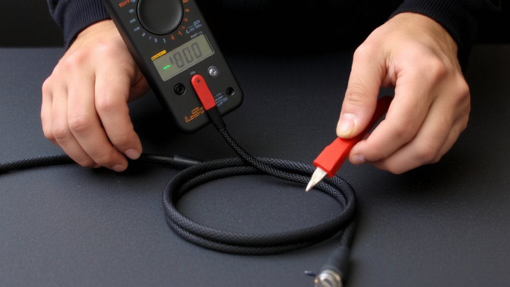
A broken connection can halt your entire workflow, especially when it’s hiding in a cable you rely on daily. Cable continuity means there’s an unbroken path for current to flow from one end to the other. Without it, signal integrity suffers-data slows or drops, and devices fail to communicate. High electrical resistance in a damaged wire can mimic partial continuity, letting some power through but degrading performance over time. You might not notice at first, but intermittent faults grow worse. Testing continuity helps catch these flaws early. It’s essential for maintaining reliable connections in peripherals, chargers, and data cables. While not every cable failure is visible, poor conductivity often is detectable with simple tools. Still, continuity doesn’t guarantee full functionality-shielding or pair mismatches aren’t caught this way. Always combine tests with real-world usage checks. Prevention beats replacement, but know the limits: a continuous cable isn’t always a fully functional one.
Choose a Multimeter for Cable Continuity Testing
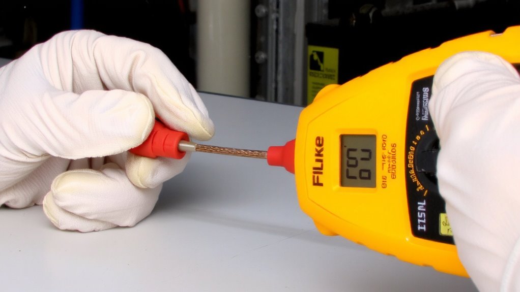
While you don’t need the most advanced meter on the market, picking the right multimeter matters when testing cable continuity-your best bet is a digital model with a dedicated continuity mode, like those from Fluke, Klein Tools, or AstroAI. These models beep instantly when a circuit’s complete, making them faster and more reliable than analog ones. Look for sturdy probe types-silicone-insulated tips offer better grip and safety, especially in tight spaces. Cheaper meters may skimp on probe durability, leading to inaccurate readings over time. Always consider calibration checks; professional-grade meters often include baseline verification features or support third-party calibration, which guarantees long-term accuracy. While consumer models save money upfront, they may lack documentation for calibration checks, risking flawed diagnostics. A solid warranty-three years or more-backs durability claims. Spend a little more for consistent performance, especially if testing cables regularly.
Set Up Your Multimeter for Continuity Mode
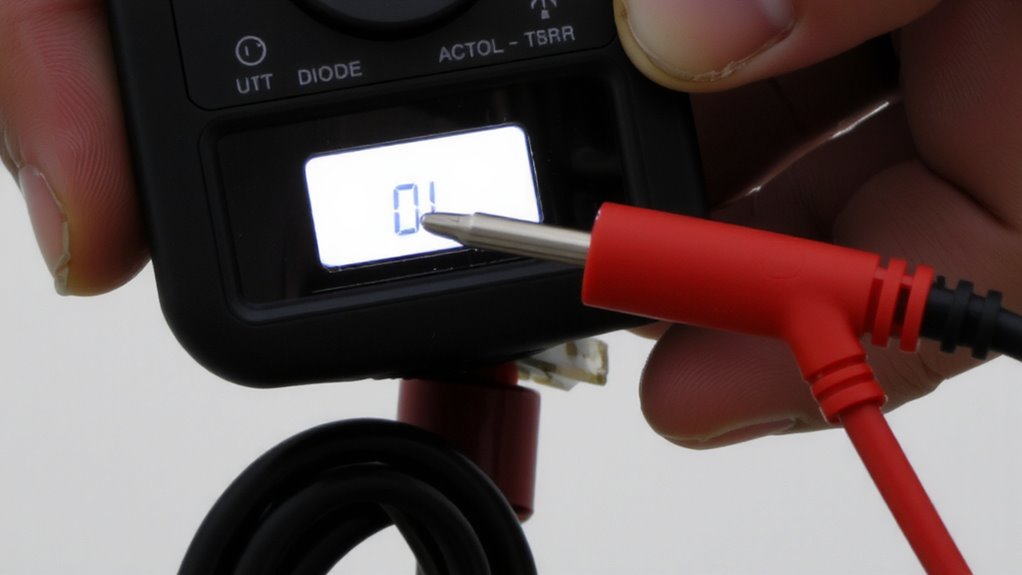
If your multimeter has a continuity setting, you’ll want to use it-it’s faster and more accurate than resistance mode for checking cable integrity. Turn the dial to the continuity symbol (usually a diode with sound waves). This mode sends a small current through the circuit and triggers a beep when the connection is complete. Proper probe placement is essential: touch one probe to each end of the conductor you’re testing, ensuring metal-to-metal contact. Most meters beep at a beep threshold of around 50 ohms, meaning continuity is detected if resistance is below that level. Don’t assume a beep always means perfect health-a loose strand might still pass. Always verify your meter’s beep threshold in the manual, as models vary. Clean probe tips and firm pressure improve accuracy. This step doesn’t confirm signal quality, just basic connectivity-so don’t over-rely on it for high-performance cables.
Test Cable Continuity Step by Step
You’ve set up your multimeter correctly-now it’s time to put it to work testing the cable. Touch the probes to both ends of the same wire inside the connector. If you hear a beep, continuity is confirmed. No beep? There may be a break, signal interference, or insulation damage. Test each wire in multi-conductor cables individually for best results.
| Step | Action |
|---|---|
| 1 | Power off connected devices |
| 2 | Insert probes into cable ends |
| 3 | Check for beep (continuity) |
| 4 | Inspect for visible insulation damage |
Hold probes steadily to avoid false readings. Long cables may show weak responses even with continuity. Don’t rely solely on sound-signal interference from nearby electronics can distort results. Always inspect outer sheathing; fraying or kinks often hide internal breaks. This process helps preserve data integrity and extends cable life, especially in high-use home office setups.
Read and Understand Your Multimeter’s Results
How do you know if your cable is truly functional? Your multimeter’s display gives the answer. A reading near zero ohms means low electrical resistance, confirming solid continuity-your cable should work. If you see OL (open loop) or very high resistance, the connection’s broken. But even with good continuity, signal interference might still disrupt performance, especially in longer runs or poorly shielded cables. Don’t assume a passing test guarantees flawless operation-some faults only emerge under actual load. Digital multimeters show precise values, so check for consistency across all conductors. Small resistance imbalances between wires can hint at internal damage. Confirm each pin-to-pin reading matches expectations for your cable type. Remember, continuity doesn’t test shielding effectiveness or data throughput. Use results as one tool, not the final verdict. Always test under real-world conditions when possible-and keep expectations realistic for older or heavily used cables.
Avoid Common Cable Testing Mistakes
While testing cable continuity might seem straightforward, skipping a few key steps can lead to false readings and costly oversights. You might think a simple beep means everything’s fine, but that’s not always true. Damaged insulation can hide breaks or shorts that only show up under stress or flexing. Always inspect the whole cable visually before and during testing. Loose connections often give intermittent results, so wiggle each end while monitoring the multimeter. Don’t forget to power down the circuit-live testing risks damaging your multimeter or giving inaccurate feedback. Set your multimeter to continuity mode correctly and confirm it works by touching the probes together first. Remember, even a good continuity reading won’t catch every fault, especially if resistance is high due to poor joints. For reliable long-term performance, combine testing with thorough inspection.
On a final note
You should test cable continuity regularly to catch wear early and extend gear life. Most multimeters with a continuity beeper and 200 Ω resistance range work well-look for auto-ranging and sturdy probe tips. A clear tone means solid connection; no sound suggests breaks. Don’t rely solely on visuals-internal damage hides easily. Cheap meters may give false readings, so verify results across multiple points. Always power off devices first to avoid damage.